
CMM Equipment for Precision Machining:
What the Data Actually Tells You
When a supplier says “±0.005mm tolerance,” that claim is only as good as the CMM equipment behind it. A coordinate measuring machine does not guess — it maps physical geometry against a nominal CAD model and reports deviations in microns. Understanding what a CMM measures, which CMM equipment spec matters, and how to read the output tells you whether a dimensional report is evidence or decoration.
This guide covers how CMM measurement works in a production CNC environment, what the Zeiss Contura MPE specification means in practice, and how to interpret Cpk values derived from CMM data. It is written for engineers sourcing precision machined parts from Vietnam, not for metrologists building labs.
What CMM Equipment Actually Measures
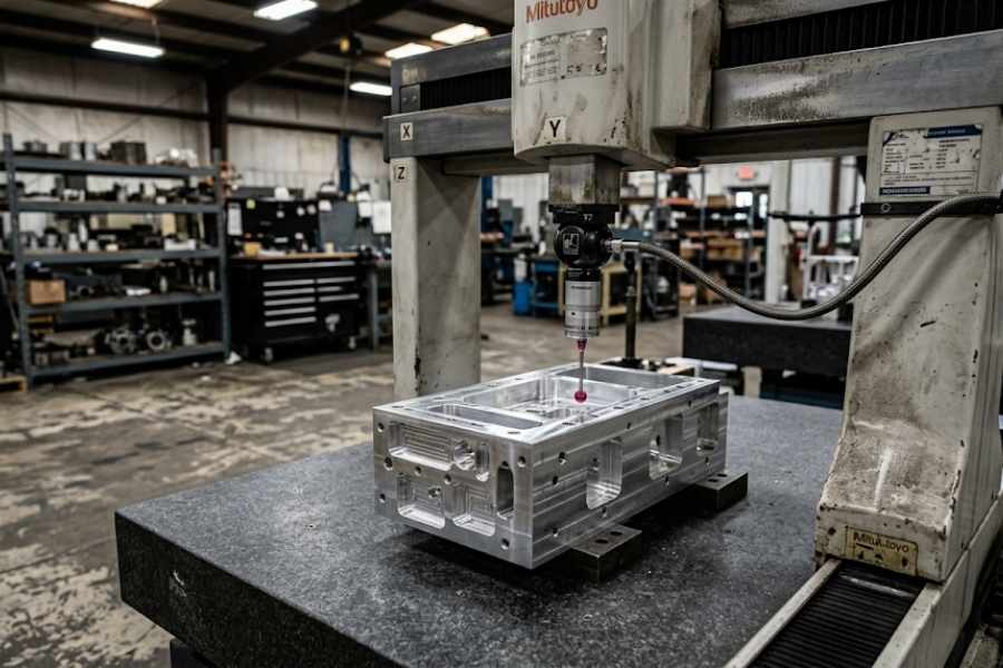
A coordinate measuring machine captures the X, Y, Z position of points on a part surface using a calibrated probe. The machine compares those measured points to the nominal geometry in your drawing — either a 2D print or 3D CAD — and calculates deviations for every controlled dimension.
The output is not pass/fail on a single number. A CMM measurement report lists every toleranced feature: its nominal value, actual measured value, deviation, and whether it is within tolerance. For a typical precision machined part with 20–50 controlled dimensions, that is 20–50 individual data rows.
- Linear dimensions — bore diameter, hole position, wall thickness
- Geometric tolerances — flatness, circularity, cylindricity
- Profile of a surface — complex contoured features
- True position of hole patterns relative to datum
- Perpendicularity, parallelism, angularity to datum planes
- Runout — total and circular, on turned parts
- Surface roughness (Ra) — measured by profilometer, not the probe stylus
- Thread form verification — go/no-go gauge or optical comparator
- Visual cosmetic inspection — trained inspector under calibrated light
- Functional assembly fit — physical fitment check on first articles
- Hardness — separate Rockwell or Vickers instrument required
At VNcontX, coordinate measurement covers 100% first article inspection on every new order, plus statistical in-process sampling on production runs. The CMM equipment we run — Zeiss Contura for primary dimensional verification and Mitutoyo instruments for in-process CMM measuring — operates on a calibrated schedule tied to our ISO 9001:2015 procedures. Go/no-go gauges confirm thread features before any dimensional scan begins.
Zeiss Contura Specs: What MPE 0.9+2.5L/1000 Means
The Zeiss Contura we run carries a maximum permissible error (MPE) specification of 0.9 + 2.5L/1000 μm, where L is the measured length in millimeters. This is the ISO 10360-2 formula for volumetric length measurement accuracy.
Practical example: Measuring a 100mm feature — MPE = 0.9 + (2.5 × 100)/1000 = 0.9 + 0.25 = 1.15 μm maximum error at that length. At 200mm, MPE = 1.4 μm. Well below the ±5 μm uncertainty needed to reliably verify ±0.005mm part tolerances.
The industry rule is that measurement system uncertainty should be no more than 1/4 to 1/5 of the part tolerance being verified. For a ±0.005mm (±5 μm) tolerance, you need an instrument with uncertainty under 1.25 μm on the relevant feature size. The Zeiss Contura satisfies this requirement on features up to approximately 150mm — which covers the vast majority of precision machined components.
| Feature Length | Zeiss Contura MPE | 1/4 Rule for ±0.005mm Tol. | Result |
|---|---|---|---|
| 50 mm | 1.025 μm | ≤ 1.25 μm | ✓ Within spec |
| 100 mm | 1.15 μm | ≤ 1.25 μm | ✓ Within spec |
| 150 mm | 1.275 μm | ≤ 1.25 μm | ⚠ Marginal — discuss |
| 200 mm | 1.4 μm | ≤ 1.25 μm | Tighten tolerance needs review |
For parts with ±0.003mm precision tolerance on specific features, we flag those during DFM review. Sub-micron feature verification on small geometries is achievable on the Contura; features longer than ~80mm at ±0.003mm require a separate discussion about measurement strategy and fixturing.

Reading Cpk from CMM Data: Process Capability Explained
A CMM measurement on a single part tells you whether that part conforms. Cpk tells you whether your process conforms — that is, whether the machine consistently produces parts within tolerance, not just whether today’s sample happened to pass.
Cpk (process capability index) is calculated from a sample of CMM measurements, typically 25–50 consecutive parts at the start of a production run or during an established run. The formula uses the measured mean and standard deviation of a dimension against its tolerance limits:
Cpk = min[ (USL − X̄) / 3σ , (X̄ − LSL) / 3σ ]
USL = upper specification limit | LSL = lower specification limit | X̄ = mean | σ = standard deviation
| Cpk < 1.00 | Process out of control — defects expected |
| 1.00–1.33 | Marginally capable — monitor closely |
| 1.33–1.67 | Capable — standard for commercial machining |
| ≥ 1.67 | VNcontX target — Six Sigma adjacent |
A Cpk of 1.67 means the process mean sits more than 5 standard deviations from either tolerance limit. Statistically, that yields fewer than 0.57 defective parts per million opportunities — before inspection catches them.
For a supplier running Cpk 1.00 on a ±0.005mm tolerance, you are statistically guaranteed rejects in a production run. The dimensional data will show you the difference immediately — a tight bell curve vs. a spread that nearly touches the spec limits.
Our dimensional reports include Cpk values on critical dimensions for production runs of 10 pieces or more. For lower-volume orders (prototype, 1–9 pcs), we report measured values and deviations per feature rather than statistical capability — there is not enough sample size for meaningful Cpk on a 3-piece order.
What a Real CMM Measurement Report Contains
Vague inspection reports are a risk flag. A report that says “all dimensions conform” without showing measured values against nominal is not a CMM report — it is a paper declaration. Here is what a properly structured dimensional report includes — and if you need a walkthrough of how to interpret each column, our cmm inspection report buyer guide covers that in detail:
| Report Section | What It Shows | Why Buyers Need It |
|---|---|---|
| Header | Part number, revision, material, CMM serial, probe ID, date/time, operator | Traceability — confirms which machine and calibration state was used |
| Feature list | Each controlled dimension: nominal, actual, deviation, tolerance, pass/fail | Evidence — not a summary claim, actual numbers per feature |
| True position | Hole center deviation in X and Y from drawing datum, vs. position tolerance zone | Critical for assembly fit — a hole that passes diameter check can still fail position |
| GD&T callouts | Flatness, perpendicularity, runout — measured zone vs. tolerance zone | Confirms form and orientation meet drawing intent, not just size |
| Cpk data | Statistical process capability on critical dims, sample size noted | Production assurance — individual parts pass but process may be drifting |
| Sign-off | QC inspector name, date, supervisor review signature | Accountability — report is a quality record, not an auto-generated file |
VNcontX issues dimensional reports in PDF format with CSV raw data file on every order. You can request a sample anonymized report before placing an order — contact duc.nguyen@vncontx.com. For orders requiring full First Article Inspection (FAI), the coordinate measurement data forms the dimensional section of the FAI package alongside material CoC and surface finish records.
CMM Measurements in a Vietnam CNC Production Workflow
Coordinate measurement is not a standalone quality gate — it is one layer in a staged inspection workflow. In CMM manufacturing environments, how a shop uses CMM equipment during production is as important as the machine specification itself. The measurement strategy — when to run 100%, when to sample, and how to respond to drift — determines whether the CMM data is actionable or just paperwork.
When: First piece off every new order
CMM coverage: 100% of all toleranced dimensions on drawing
Gate: Production does not continue until FAI is approved. Drawing discrepancies, setup errors, or tool compensation issues are caught here before any quantity is run.
When: During production run, frequency per AQL table or order risk level
CMM coverage: Critical dimensions only — typically 5–10 features per sample
Purpose: Detect tool wear drift, thermal compensation shifts, or fixturing movement before a full batch is non-conforming. Mitutoyo gauging handles spot checks; full CMM is triggered when a feature is at risk of drifting.
When: 100% before packing and shipment
Scope: Visual + functional check; dimensional re-check on parts flagged during in-process sampling
Documentation: Final inspection sign-off on the shipment record, dimensional report issued with packing list.
If CMM measurement identifies an out-of-tolerance condition at any stage, we issue an NCR (non-conformance report) internally and notify the buyer before shipment — not after.
The NCR documents the deviation magnitude, root cause analysis, and corrective action (rework, remake, or disposition). A corrected dimensional report accompanies any reworked parts.
Questions We Get About CMM Equipment and Measurement
Request a CMM Report Sample or Technical Quote
Send your drawing. We will review tolerance requirements, confirm CMM coverage against your CTQ features, and include a sample anonymized CMM report with the quote.
Request a Technical Quote → Talk to an Engineer →duc.nguyen@vncontx.com | | Bình Chánh, Ho Chi Minh City
